


Abstract
Objectives
An ongoing prospective study to investigate failing metal-on-metal hip prostheses was commenced at our centre in 2008. We report on the results of the analysis of the first consecutive 126 failed mated total hip prostheses from a single manufacturer.
Methods
Analysis was carried out using highly accurate coordinate measuring to calculate volumetric and linear rates of the articular bearing surfaces and also the surfaces of the taper junctions. The relationship between taper wear rates and a number of variables, including bearing diameter and orientation of the acetabular component, was investigated.
Results
The measured rates of wear and distribution of material loss from the taper surfaces appeared to show that the primary factor leading to taper failure is the increased lever arm acting on this junction in contemporary large-diameter metal-on-metal hip replacements.
Conclusions
Our analysis suggests that varus stems, laterally engaging taper systems and larger head diameters all contribute to taper failure.
Article focus
What are the factors leading to debris release from modular junctions in contemporary large-diameter metal-on-metal (MoM) total hip replacements (THRs)?
Key messages
Significant amounts of metal debris are released from modular junctions
Taper wear appears to be unrelated to wear of the bearing surface
Taper wear may be more likely in systems with larger diameter heads, larger head offsets and varus stems
Strengths and limitations
This is the first paper to describe in detail the volumetric loss of debris from modern THRs
The results have been obtained from examination of one of the largest modern MoM THR explant collections in the world
As it reports results from a failed sample group it is inherently biased
Introduction
The last four years have seen an increasing number of reports of adverse soft-tissue reactions following metal-on-metal (MoM) arthroplasty of the hip.1-3 At first, there appeared to be no correlation between the incidence of these tissue reactions and either MoM total hip replacement (THR) or hip resurfacing.4 The 2011 report of the National Joint Registry for England and Wales (NJR)4 published failure rates of 29.0% for the Articular Surface Replacement (ASR; DePuy, Leeds, United Kingdom) THR at six years, in contrast to a 9.6% failure rate for the ASR resurfacing.5 A clear difference in the performance of the two systems despite identical bearing surfaces. Some observers have stated that the failure of the ASR THR can be linked directly to the flawed design of the ASR acetabular component, leading to higher friction that propagates distally, stressing the modular junction and leading to release of debris from the taper junction.6 However, joint registry reports from England and Wales and Australia suggest that this issue is not specific to the ASR, but that there is a deeper underlying problem.4,6 Both registries have shown that MoM THRs in general have not performed as well as conventional bearing surfaces. As shown in the Australian registry,6 this difference in revision rates becomes more emphasised as diameter of the bearing increases. Garbuz et al,7 Langton et al8 and Beaulé et al9 have shown evidence that blood metal ion concentrations are elevated in THRs compared with their resurfacing counterparts in studies involving the Durom (Zimmer, Warsaw, Indiana), ASR and Conserve Plus systems (Wright Medical, Memphis, Tennessee), respectively. A recent prospective study10 in the United Kingdom comparing the Birmingham Hip Resurfacing (BHR; Smith & Nephew, Warwick, United Kingdom) with the BHR THR was terminated due to unacceptably high metal ion levels in patients receiving the THRs.
Retrieval studies have shown evidence of damage at the head–neck modular junction in patients suffering catastrophic tissue damage in association with minimal wear of the bearing surface.8,11 In the past, many authors have proposed that the mechanism of taper failure is primarily electrochemical in nature.10,12 However, previous analyses have been carried out largely using a simple visual quantification of “corrosion”. In this study we aimed to quantify the material loss from tapers, in order to identify risk factors for taper failure and in so doing propose a mechanism that may precipitate failure.
Materials and Methods
Equipment
At our centre, we have carried out a continuing prospective investigation into the failure of MoM hip devices since 2008. All DePuy MoM THRs received at Newcastle University up to September 2011 underwent full volumetric and linear wear assessment of the femoral and acetabular bearing surfaces as well as the articular surfaces of the taper junctions. This was done using a coordinate measuring machine (CMM) (Legex CMM; Mitutoyo, Tokyo, Japan) with an accuracy of 0.8 µm. The technique we used to obtain volumetric measurements of the bearing surfaces of MoM components has previously been published.13,14 We used a custom designed Matlab programme (The Mathworks Inc., Natick, Massachusetts) to analyse the taper surfaces. Using gravimetric analysis as the benchmark measurement technique, our taper analysis was found to be accurate to approximately 0.2 mm3. DePuy components only were included in this analysis. The justification in limiting the research to DePuy products in the first instance was to avoid confounding factors including gross variations in metallurgy, engineering tolerances and material combinations of various stem–head combinations used by different manufacturers.
Patients and components
Only components with satisfactory radiographs suitable for analysis of acetabular component orientation using Ein-Bild-Roentgen-Analyse (EBRA) software (University of Innsbruck, Innsbruck, Austria)15 were included as well as those with a known reason for revision, mated femoral stem details and length of time in vivo. There were 111 tapers available for analysis in total. The majority of hips (n = 68, 61%) were obtained from University Hospital of North Tees, where three consultant hip surgeons (CT, RL and an author, AVFN) performed the primary and revision surgeries. The demographics of the patients from whom the components were taken are provided in Table I. In a minority of cases where femoral stems were available, the trunnions also underwent the same analysis. Implants were received from centres in the United Kingdom and United States. The majority of implants (n = 104) were revised secondary to adverse reactions to metal debris (ARMD), the diagnosis of which was based on a combination of clinical history, examination and macroscopic and histological appearance of tissues at revision surgery.2
Table I
Details of the samples analysed
| ASR XL* | Articuleze (Pinnacle) | ||
|---|---|---|---|
| Number of hips | 63 | 48 | |
| Male:female | 23:40 | 14:34 | |
| Median age at implantation (yrs) (range) | 55 (42 to 73) | 66 (55 to 73) | |
| Median time in vivo (mths) (range) | 33 (11 to 64) | 42 (12 to 75) | |
| Reason for revision (n, %) | |||
| Adverse reaction to metal debris | 61 (96.8) | 43 (89.6) | |
| Loosening of the femoral component | 1 (1.6) | 2 (4.2) | |
| Loosening of the acetabular component | 1 (1.6) | 1 (2.1) | |
| Unexplained pain | 0 (0) | 2 (4.2) | |
-
* ASR, Articular Surface Replacement
In this study, the term “trunnion” refers to the intended articular area of the femoral stem (i.e., the “male” component of the modular junction). The term “taper” describes the area attached to the femoral head that is intended to contact the trunnion. It refers to either a sleeve that inserts into the femoral head (as with the ASR XL head system) or simply to the internal cone of the head in systems not using a sleeve adaptor (such as the Pinnacle system (DePuy) that uses an “Articuleze” femoral head).
All the femoral heads in the study had been used in combination with DePuy stems that were manufactured from titanium (Ti)-aluminium (Al)-vanadium (V) alloy (Ti6Al4V). These stems were Corails and Summits (both DePuy).
As all but one of the implanted Pinnacle devices had a bearing diameter of 36 mm (the exception being 40 mm), the Pinnacle devices were initially analysed separately from the ASRs. The ASR bearing diameters varied in size, with a median of 22.75 mm (39 to 57). In this way two groups were created and analysed as separate entities in order to eliminate potentially confounding variables: 1) the ASR group (ASR bearing surface with Corail or Summit stems; n = 63); and 2) the Pinnacle group (Pinnacle MoM system with Corail or Summit stems; n = 48).
Visual inspection
In modular junctions with obvious macroscopic changes there was invariably a localised site of maximal damage where the taper had appeared to engage. The distance of this level of damage from the articular bearing surface we refer to from here on as the taper engagement level (TEL) (Figs 1 and 2). Using simple trigonometry and accounting for the anteroposterior plane only, we calculated the maximal possible lever arm acting on the TEL in the superior inferior direction. Figure 3 shows how this effective horizontal lever arm (HLA) distance was calculated. The lever arm distance is increased by an increasing head offset, increasing bearing diameter and an increasingly varus neck shaft angle.
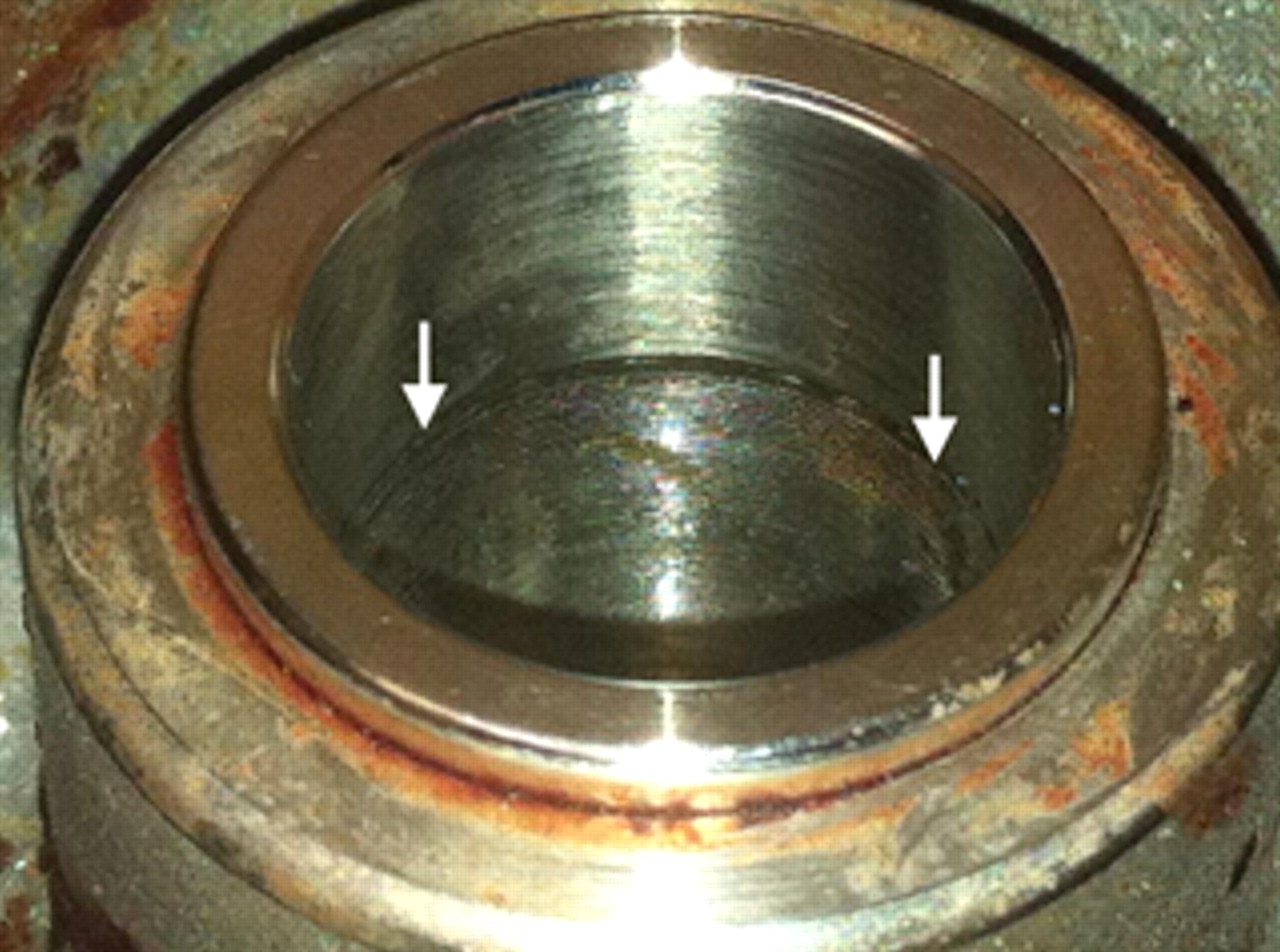
Fig. 1
Photograph of an Articular Surface Replacement (ASR) XL head with Corail taper adaptor. The arrows represent the taper engagement level.
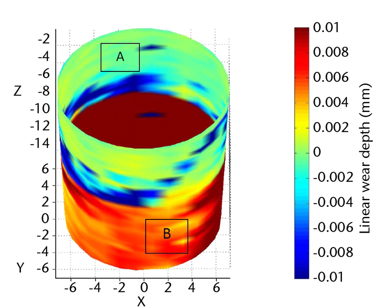
Fig. 2
Image from coordinate measuring machine (CMM) analysis of the Corail taper seen in Figure 1. The boldest red areas indicate the areas of maximal wear (i.e., the taper engagement level).
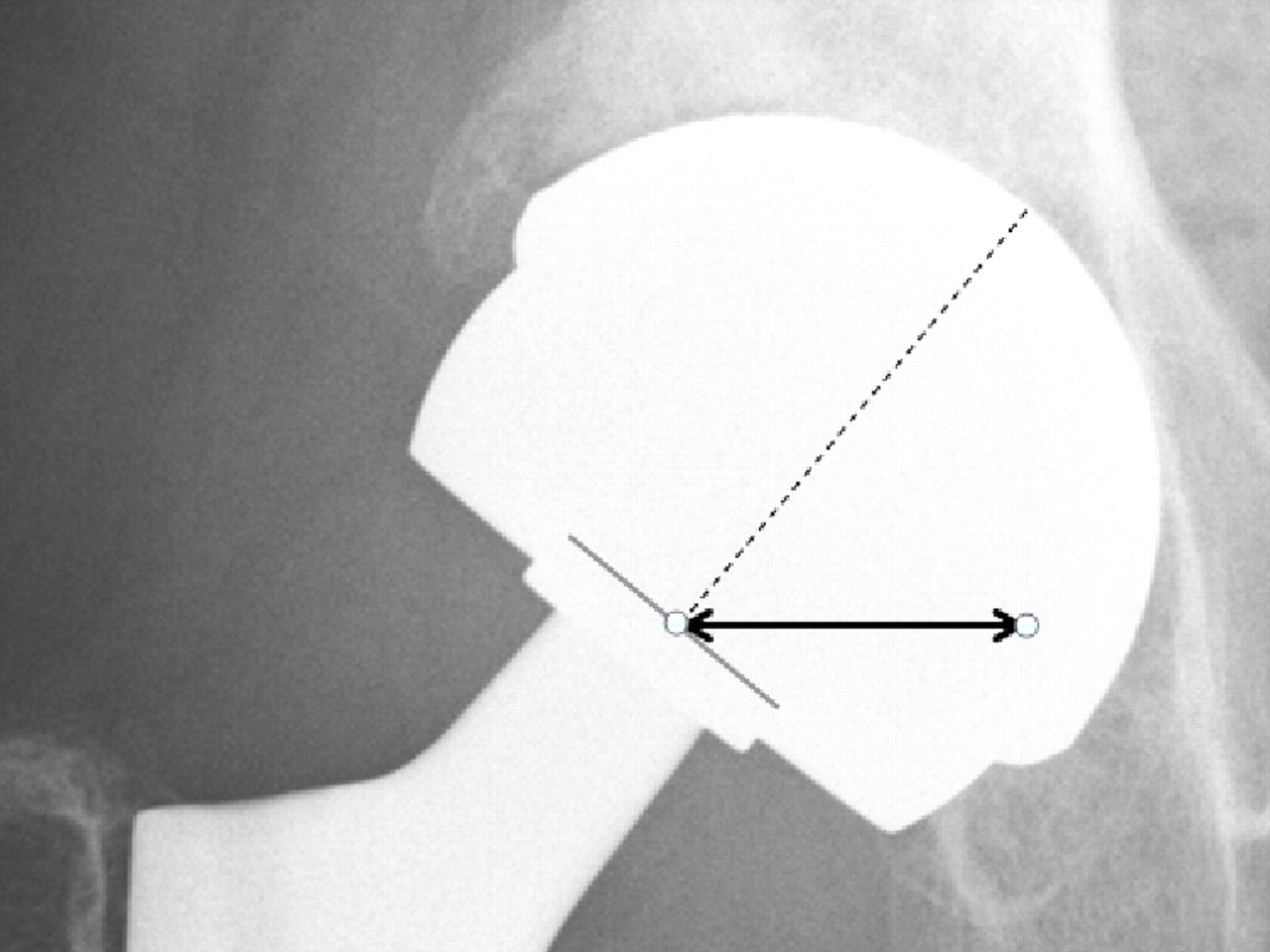
Fig. 3
Radiograph showing the measurement of the horizontal lever arm (HLA) distance (bold black line). The HLA is the horizontal distance (in mm) from a line through the axis of the neck to the tip of the bearing surface (broken line) and the centre of the taper engagement level.
Statistical analysis
The linear and volumetric wear rates of the tapers were examined using the Shapiro-Wilk test for normality and found to be non-parametric. Spearman rank correlation was therefore used to examine the relationships between taper wear rates and a number of variables: taper angle (obtained from unworn areas); bearing diameter; angles of inclination and anteversion of the acetabular component; the distance from the centre of rotation (COR) to the TEL; the HLA distance; volumetric bearing surface wear rates and nominal head offset. The effect of clearance on taper wear was also examined using the same method. A p-value < 0.05 was considered statistically significant.
Results
A total of 111 hips were available for analysis. There were 63 ASRs XL heads (12 Summit stems and 51 Corail stems) and 48 Articuleze heads (47 Corails and one Summit). A total of 38 tapers (34%) exhibited no identifiable surface change on visual inspection. Volumetric and linear wear analysis showed little or no distinction between these tapers when compared with unused, sterile tapers used as control specimens. Wear depths were less than 5 µm in each case. These components were revised secondary to the effects of excessive bearing surface wear, unexplained pain or pain due to loosened femoral/acetabular components. Tables II and III show the differences in tapers found to have obvious TELs/surface change and those without. The majority of retrieved specimens (n = 73) were found to have grossly abnormal taper surfaces. The patterns of surface changes were remarkable in their similarity. Figure 1 shows the macroscopic appearance of a typical sample. Essentially an area of significant damage could be seen (and often even palpated) in a localised circumferential band that corresponded to the insertion of the base of the trunnion (Figs 1 and 2). Proximal to this band (in anatomical terms), the trunnion had left an imprint of its machining grooves (Fig. 2). Scanning electron microscopy (SEM) images confirmed this phenomenon (Fig. 4). CMM wear analysis showed that the most damaged area in visual terms corresponded to the area with the maximal wear depths (Fig. 2). This was identified as the TEL. The areas in which the CMM showed there had been material loss were analysed using the SEM. It appeared that the ridges formed by the trunnion grooves had been flattened somewhat in these regions. Multiple pits had developed. The pits were localised, approximately ten microns in diameter and appeared to be partially filled with inclusion bodies (Fig. 5). Due to the imbedded particulate matter, it appeared likely that the surface changes had occurred primarily due to a mechanical process. Energy dispersive X-ray spectroscopy (EDX) analysis showed that the pits were rich in chromium and the presence of small amounts of chlorides and oxides suggested that corrosion was occurring locally. The surface immediately surrounding these pits showed no changes from the manufactured alloy. There was no difference identified between the patterns of surface change between the ASR and Articuleze specimens.
Table II
Details for the Articular Surface Replacement (ASR) standard tapers in which a taper engagement level (TEL) was easily identified versus those in which there was no such finding (and the components were indistinguishable from a sterile component)
| Characteristics (median and range) | TEL identified (n = 48) | No TEL identified (n = 15) | p-value* | ||
|---|---|---|---|---|---|
| Duration in vivo (mths) | 34 (14 to 64) | 29 (11 to 60) | 0.232 | ||
| Taper angle (°) | 5.670 (5.568 to 5.798) | 5.645 (5.592 to 5.698) | 0.084 | ||
| Diametral clearance (µm) | 83.4 (72.0 to 116) | 84.0 (72.6 to 114.2) | 0.328 | ||
| Horizontal lever arm distance (mm) | 18.90 (9.37 to 25.48) | 17.74 (10.79 to 20.68) | 0.153 | ||
| Size (mm) | 45.94 (38.49 to 52.51) | 44.57 (40.51 to 49.10) | 0.262 | ||
| Surface wear (mm3/yr) | 2.32 (0.46 to 82.5) | 2.87 (0.59 to 10.75) | 0.517 | ||
-
* Mann-Whitney U test
Table III
Details of the Articuleze tapers in which a taper engagement level (TEL) was easily identified versus those in which there was no such finding (and were indistinguishable from a sterile component)
| Characteristics (median and range) | TEL identified (n = 25) | No TEL identified (n = 23) | p-value* | ||
|---|---|---|---|---|---|
| Duration in vivo (mths) | 42 (12 to 74) | 43 (12 to 75) | 0.961 | ||
| Taper angle (°) | 5.639 (5.584 to 5.685) | 5.629 (5.557 to 5.672) | 0.471 | ||
| Diametral clearance (µm) | 88.8 (70.2 to 112.8) | 89.6 (70.2 to 119.4) | 0.855 | ||
| Horizontal lever arm distance (mm) | 17.94 (10.26 to 24.53) | 16.04 (12.34 to 20.89) | 0.007 | ||
| Surface wear (mm3/yr) | 2.03 (0.51 to 6.29) | 3.57 (0.51 to 13.67) | 0.069 | ||
-
* Mann-Whitney U test
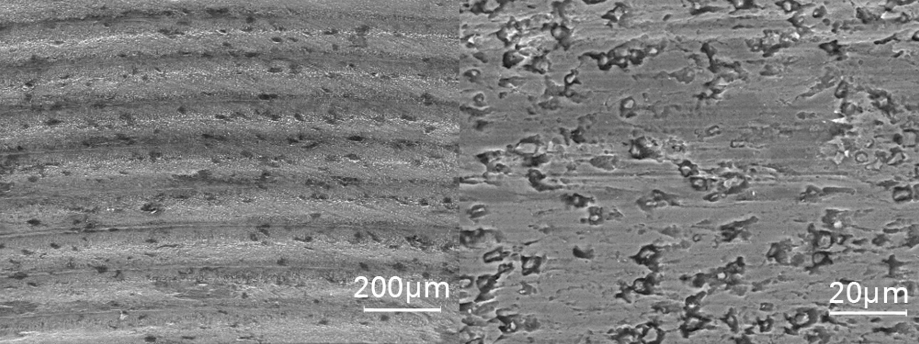
Fig. 5
Scanning electron microscopy (SEM) images of a taper that has experienced greater wear, at the same level of magnification as in Figure 4 (left), showing that the peaks and troughs caused by the impression of the machining grooves have been sheared off, leading to significant material loss, and at a higher magnification (right), showing the formation of pits with inclusion bodies, probably as a result of mechanical wear
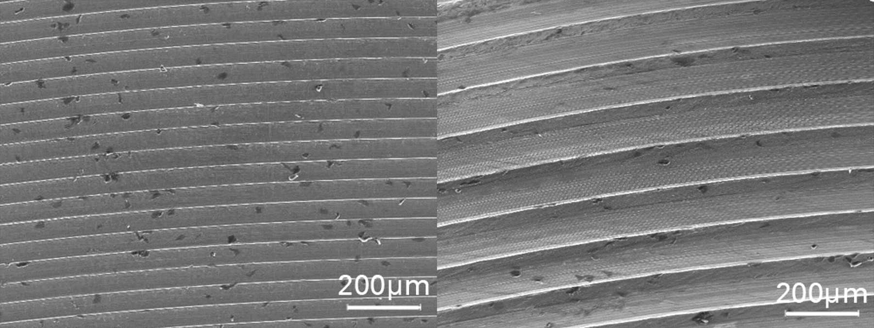
Fig. 4
Scanning electron microscopy (SEM) images of an area of unworn manufactured taper surface (left) and an area deeper in the same taper that shows the imprint of the machining grooves of the trunnion (right). Note: images are at the same level of magnification.
The effect of bearing surface wear, clearance and offsets
Taper linear and volumetric wear rates appeared to be unaffected by variations in clearance or bearing surface wear rates. There was a trend towards increasing taper damage and increasing head offset (Table IV).
Table IV
Relationships between the measured volumetric wear rates of the taper surfaces and the examined variables. Results are shown as Spearman’s rank correlations with p-values in parentheses. Significant results are in bold
| Articuleze (n = 48) | ASR* XL (n = 63) | ||
|---|---|---|---|
| Surface wear | -0.236 (p = 0.136) | 0.003 (p = 0.982) | |
| Bearing diameter | - | 0.150 (p = 0.249) | |
| Taper angle | 0.235 (p = 0.108) | 0.383 (p = 0.002) | |
| Head offset | 0.323 (p = 0.027) | 0.278 (p = 0.091) | |
| Distance (taper engagement level to centre of rotation) | 0.321 (p = 0.034) | 0.363 (p = 0.006) | |
| Horizontal lever arm distance | 0.408 (p = 0.008) | 0.380 (p = 0.004) | |
-
* ASR, Articular Surface Replacement
The effect of bearing diameter
When the two groups were compared directly, the ASR tapers were found to have significantly greater rates of volumetric and linear wear than the Pinnacle tapers (Table V).
Table V
Comparison of linear and volumetric wear rates of the Articuleze versus Articular Surface Replacement (ASR) XL tapers
| Articuleze (n = 48) | ASR XL (n = 63) | p-value* | ||
|---|---|---|---|---|
| Median linear wear rate (µm/yr) (range) | 1.39 (0.24 to 106.6) | 5.92 (0.57 to 32.78) | < 0.001 | |
| Mean volumetric wear rate (mm3/yr) (range) | 0.127 (0.01 to 3.15) | 0.44 (0.02 to 8.34) | < 0.001 | |
-
* Mann-Whitney U test
Analysis of the samples as a whole
Figure 6 shows the significant relationship between HLA distance and linear wear rate of the tapers when all samples were included in the analysis (Spearman rank correlation = 0.527, p < 0.001). The same rank correlation using only the Articuleze group (to control for bearing diameter as a variable) was 0.472 (p = 0.002). For the ASR XL group it was 0.416 (p = 0.002).
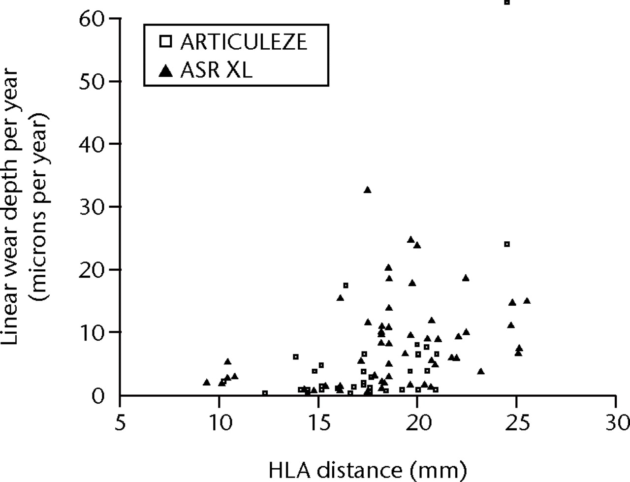
Fig. 6
Scatter graph showing the relationship between linear wear rates of the taper surfaces and the horizontal lever arm (HLA) distance (all taper components included) (ASR, Articular Surface Replacement).
The effect of orientation of the acetabular component
No significant relationship was identified between cup inclination or anteversion and taper wear (Table VI). This was consistent with the lack of correlation between surface wear and taper wear (Table IV).
Table VI
Spearman rank correlation of taper wear rates versus acetabular component angles of inclination and anteversion. All samples were included in the analysis. p-values are given in parentheses
| Linear wear rate (µm/yr) | Volumetric wear rate (mm3/yr) | |
|---|---|---|
| Inclination (°) | -0.073 (p = 0.564) | -0.071 (p = 0.572) |
| Anteversion (°) | -0.013 (p = 0.916) | -0.013 (p = 0.917) |
Trunnion analysis
There were 11 Corail stems available for analysis. Volumetric analysis proved difficult. This was due to the apparently less tightly controlled manufacturing form of the trunnions (which was confirmed on sterile, unused specimens). Despite this limitation, wear depths appeared to be indistinguishable from manufacturing variation, in that there was no measurable wear over the intended articular area of the trunnions. We were unable to measure the trunnions base in seven of the 11 samples as damage had occurred during extraction. Of the four loose stems that had not suffered damage during explantation, there was no measurable wear. SEM analysis of the trunnions also identified no obvious areas of wear or corrosion although further investigation of the retrieved stems is ongoing.
Discussion
This paper contains an in-depth examination of the modular junction of failed contemporary MoM THRs. It is the largest of its kind in existence. In past research papers taper junctions have been examined using visual scales.12,16 To our knowledge, no accurate quantification of volumetric material loss has previously been published. The results presented in the current paper show that significant volumetric material loss can take place at the modular junctions of modern large diameter THRs. This material loss can exceed that taking place at the bearing surface. The consistent pattern and location of maximal damage on the female taper is consistent with mechanical incompetence.
Is taper failure due to the MoM bearing surface
It is unquestionable that conventional THR is an extremely successful procedure. The 10-year survival of the most common hip prostheses used in Sweden is now over 95%.17This is in contrast to the latest published results of large-diameter MoM THR systems that offer a 13.6% revision rate at seven years.4,6 The smaller 28 mm Metasul MoM bearing (Zimmer, Warsaw, Indiana) however appears to be functioning relatively successfully in a number of patients at long-term follow-up.18 It therefore seems unlikely from the evidence that the MoM bearing surface per se is the problem with the latest generation of MoM THRs. The stems associated with failure in this series are, without exception, titanium alloys. The practise of coupling a Ti stem with a CoCr taper has raised concerns of mixed material combinations leading to galvanic corrosion.19 However, Ti stems have been implanted with CoCr heads for many years with limited reports of gross clinical failures.20 It is unlikely either, therefore, that it is simply a mixed material coupling that is the root cause of failure. Indeed, previous reports of taper junction failures have included similar metal modular hips.12
So why are tapers failing in the 21st century? There have been three obvious changes to the most recent designs of large-head MoM hips that we believe to be of paramount importance.
1. A change in trunnion dimensions
Trunnions have become shorter in length. The trade name of the DePuy taper of the standard group in this study is in fact the “Articuleze Mini Taper” (AMT). This is not a design change specific to DePuy. In fact, most commonly used trunnions are now only 10 mm to 12 mm in length. These changes were brought about to reduce the trunnion’s ‘skirt’ in order to increase the impingement-free range of movement. However, a reduction in length means that the base of the trunnion now often sits inside the taper. This increases the possibility of edge loading of the trunnion base. The subsequent increase in localised stress likely explains the circumferential pattern of surface damage seen on the standard stem taper surfaces in this investigation. Trunnions have also been slimmed down from 16 mm/14 mm diameter cones to the commonly used 14 mm/12 mm cones. A smaller diameter taper means less surface area for a successful interference fit and increases the potential for micromotion.
2. A change in trunnion surface
Most contemporary trunnions now have a ridged surface that has been machined into the material in order to accommodate ceramic heads. This makes financial sense for companies so they can manufacture one stem for multiple bearing surfaces. The machining grooves of the standard trunnion had left an imprint on the failed tapers in this study. We speculate that this plastic deformation of the taper surfaces leads to altered contact stresses and a potential for increased wear. The localised pits we observed may then allow secondary corrosion to take place over a greater surface area.
3. A trend for increasing head size
Larger diameter bearings have the potential to produce less wear21 and are less likely to dislocate.22 Understandably, these benefits proved irresistible to industry and surgeons alike. While head sizes increased through the years from 22 mm versions to a standard size male resurfacing femoral component of approximately 52 mm, there was no compensatory change in the morphology of the taper junction. In fact, as head sizes increased, taper junction sizes decreased (as described above). The findings of this retrieval analysis suggest that, while bearing diameter is significant, it is far from the only factor. In the ASR XL group in this study, head size was only weakly associated with taper wear rates. HLA distance proved to be the strongest predictor of taper wear rate in both groups. Consistent with this finding, when bearing diameter was eliminated as a variable (examination of the Articuleze group separately), the effect of an increased HLA distance became even more significant.
Frictional torque
An explanation for the damage observed at the modular junctions of large diameter hip systems could be the increased frictional torque that is generated by the bearing surfaces. This mechanism of failure has support from experimental studies involving metal-on-polymer articulations.23 However, we can offer no physical evidence of a torsional force from this series of retrieved MoM explants. We have described in our previous work that the thumb printed wear pattern consistently identified on the tapers matched with SROM stems.8 This pattern of surface change is contrary to the idea that the femoral components are turning on the trunnion. Moreover, in this study the site of maximal taper damage was always found on the opposite side of the head to the location of the wear scar of the head (generally the posteroinferior aspect of the taper). This important finding implies a toggle effect with the mechanical action itself causing damage to the taper surface and opening the junction to the potential corrosive effects of physiological fluids. Finite element analysis studies of the stress distribution on large diameter THRs are consistent with the location of damage identified on the tapers in this study.24 Another argument against a torque issue is the absence of a significant relationship between bearing surface wear rates and taper wear rates. It is possible, however, that frictional torque initially destabilises the femoral component and then, combined with the joint reaction force, effectively screws it down the trunnion. This theory might explain why the trunnion bases have appeared to penetrate the taper surfaces so deeply at one level. Once the TEL is firmly established, it may be that a toggle effect then predominates.
Manufacturing tolerances
Small variations in the taper and trunnion angles may cause a defined TEL when the head is impacted at primary surgery. Tapers and trunnions are manufactured to a specific tolerance in terms of angles and dimensions. The tolerance band for the taper angles in this series is ±0.069° according to the manufacturer’s data. There is evidence from a previous finite element analysis (FEA) that even tiny variations in taper and trunnion angles could be critical.25 Shareef and Levine25 stated that ‘the magnitude of micromotion…varied between 4 and 26% with increasing values of angle tolerance from zero to 1 minute on the male component’. One minute is equivalent to 0.0167°. The taper angle tolerance stated by DePuy is four times this value (Fig. 7). The same FEA report stated that ‘off axis loading caused the female component to tip such that the micromotion on one side is roughly twice that on the other side’.25 This view is consistent with our findings of taper damage more pronounced on one side than the other. It is therefore likely that taper trunnion angle mismatch is important but something we cannot investigate further until more femoral stems are analysed.
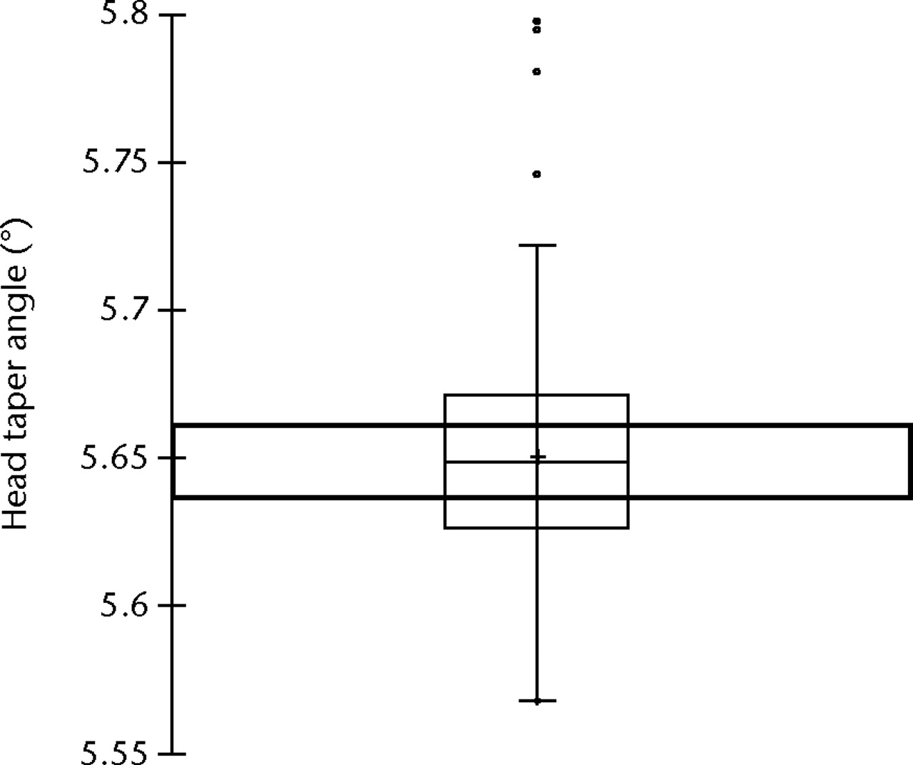
Fig. 7
Boxplot showing the distribution of head taper angle in all retrieved implants in the study. The box represents the median value and interquartile range (IQR) and + the mean value. The whiskers correspond to the limits of the data, beyond which values are considered anomalous (°, outliers; *, extreme outliers; •, upper and lower values). The bold rectangle represents the area outside of which excessive micromotion has been shown to take place by finite element analysis.25
In a perfect situation, the femoral component is impacted on the trunnion. A stable interference fit results, minimising localised stresses, the Morse taper functions adequately and there is no ingress of biological fluids. We propose a chain of events resulting in the damage observed at the taper junctions in this series. If we assume initially that the taper and trunnion angles are significantly mismatched the trunnion engages with the taper at the base of the trunnions. As a result, there is a localised concentration of stress at this level. The TEL may be put under greater stress if it is supporting a larger diameter head, is connected to a varus stem, or is in a lateralised position (increased head offset). Micromotion ensues, opening up the taper junction to body fluids. Localised corrosion, secondary to removal of material by mechanical (wear) and chemical (corrosive) processes leads to metal ion/particulate release. Further damage at the TEL leads to penetration of the trunnion further into the taper potentiating the effects described above.
Clinical implications of the mechanism of taper failure
As described above, it has been a matter of debate whether it is primarily an increase in frictional torque or an increase in moment arm that is the underlying problem with these devices. The answer to this question has real implications for the present and future of hip arthroplasty. If the primary problem is an increase in moment arm then all hard-on-hard bearing surfaces with taper configurations similar to those described here must be considered at risk of taper failure. In light of recently published literature, we have serious concerns that all large diameter bearings could indeed be affected in a similar way to those described in this paper.26 As, on the basis of commercial sensitivity, most orthopaedic manufacturers do not divulge their precise implant specifications we cannot comment in this paper on other manufacturers’ MoM devices. What can be stated is that ceramic-on-ceramic (CoC) devices were designed to medialise the TEL, with the aim being to protect the ceramic material from stresses that may cause fracture. The resultant reduction in HLA distance may also confer protection to the taper. Indeed, CoC devices should also be protected somewhat from the effects of frictional torque as the smooth wettable ceramic bearing surfaces have a lower coefficient of friction than MoM bearing surfaces.27 A ceramic taper could also be expected to be less vulnerable to the effects of wear and corrosion. In spite of this, our advice to surgeons would be to urgently re-evaluate their need to implant large diameter bearing surfaces, irrespective of the bearing surfaces, in these times of uncertainty.
The authors would like to thank Mr C. Tulloch and Mr R. Logishetty, Orthopaedic Surgeons, University Hospital of North Tees.
1 Pandit H , Glyn-JonesS, McLardy-SmithP, et al.Pseudotumours associated with metal-on metal hip resurfacings. J Bone Joint Surg [Br]2008;90-B:847–851. Google Scholar
2 Langton DJ , JamesonSS, JoyceTJ, et al.Early failure of metal-on-metal bearings in hip resurfacing and large-diameter total hip replacement: a consequence of excess wear. J Bone Joint Surg [Br]2010;92-B:38–46.CrossrefPubMed Google Scholar
3 De Haan R , CampbellPA, SuEP, De SmetKA. Revision of metal-on-metal resurfacing arthroplasty of the hip: the influence of malpositioning of the components. J Bone Joint Surg [Br]2008;90-B:1158–1163.CrossrefPubMed Google Scholar
4 No authors listed. National Joint Registry for England and Wales: eighth annual report, 2011. http://www.njrcentre.org.uk/ (date last accessed 28 March 2012). Google Scholar
5 Learmonth I. Further opinion on “Accelerating failure rate of the ASR total hip replacement. Langton DJ, Jameson SS, Joyce TJ, et al.J Bone Joint Surg [Br] 2011;93-B:1011-6”. http://www.jbjs.boneandjoint.org.uk/content/93-B/8.toc (date last accessed 28 March 2012). Google Scholar
6 Australian Orthopaedic Association. National Joint Replacement Registry: annual report, 2011. http://www.dmac.adelaide.edu.au/aoanjrr/documents/AnnualReports2011/ (date last accessed 28 March 2012). Google Scholar
7 Garbuz DS , TanzerM, GreidanusNV, MasriBA, DuncanCP. The John Charnley Award. Metal-on-metal hip resurfacing versus large-diameter head metal-on-metal total hip arthroplasty: a randomized clinical trial. Clin Orthop Relat Res2010;468:318–325. Google Scholar
8 Langton DJ , JamesonSS, JoyceTJ, et al.Accelerating failure rate of the ASR total hip replacement. J Bone Joint Surg [Br]2011;93-B:1011–1016.CrossrefPubMed Google Scholar
9 Beaulé PE , KimPR, HamdiA, FazekasA. A prospective metal ion study of large-head metal-on-metal bearing: a matched-pair analysis of hip resurfacing versus total hip replacement. Orthop Clin North Am2011;42:251–257.CrossrefPubMed Google Scholar
10 Ramaskandhan JR , MalviyaA, BowmanR, et al.What advantage is there to be gained using large modular metal-on-metal bearings in routine primary hip replacement?: a preliminary report of a prospective randomised controlled trial. J Bone Joint Surg [Br]2011;93-B:1602–1609. Google Scholar
11 Bolland BJ , CullifordDJ, LangtonDJ, et al.High failure rate with a large-diameter hybrid metal-on-metal total hip replacement: clinical, radiological and retrieval analysis. J Bone Joint Surg [Br]2011;93-B:608–615. Google Scholar
12 Goldberg JR , GilbertJL, JacobsJJ, et al.A multicenter retrieval study of the taper interfaces of modular hip prostheses. Clin Orthop Relat Res2002;401:149–161.CrossrefPubMed Google Scholar
13 Langton DJ , JoyceTJ, MangatN, et al.Reducing metal ion release following hip resurfacing arthroplasty. Orthop Clin North Am2011;42:169–180.CrossrefPubMed Google Scholar
14 Lord JK , LangtonDJ, NargolAVF, JoyceTJ. Volumetric wear assessment of failed metal-on-metal hip resurfacing prostheses. Wear2011;1:79–87. Google Scholar
15 Malviya A , LingardEA, MalikA, BowmanR, HollandJP. Hip flexion after Birmingham hip resurfacing: role of cup anteversion, anterior femoral head-neck offset and head-neck ratio. J Arthroplasty2010;25:387–391. Google Scholar
16 Goldberg JR , GilbertJL. In vitro corrosion testing of modular hip tapers. J Biomed Mater Res B Appl Biomater2003;64:78–93.CrossrefPubMed Google Scholar
17 Garellick G, Kärrholm J, Rogmark C, Herberts P. Swedish Hip Arthroplasty Register: annual report, 2010. http://www.shpr.se/en/Publications/DocumentsReports.aspx (date last accessed 4 April 2012). Google Scholar
18 Randelli F , BanciL, D'AnnaA, VisentinO, RandelliG. Cementless Metasul metal-on-metal total hip arthroplasties at 13 years. J Arthroplasty2012;27:186–192.CrossrefPubMed Google Scholar
19 Gilbert JL , BuckleyCA, JacobsJJ. In vivo corrosion of modular hip prosthesis components in mixed and similar metal combinations: the effect of crevice, stress, motion, and alloy coupling. J Biomed Mater Res1993;27:1533–1544. Google Scholar
20 Reikerås O , GundersonRB. Excellent results of HA coating on a grit-blasted stem: 245 patients followed for 8-12 years. Acta Orthop Scand2003;74:140–145.CrossrefPubMed Google Scholar
21 Smith SL , DowsonD, GoldsmithAA. The effect of femoral head diameter upon lubrication and wear of metal-on-metal total hip replacements. Proc Inst Mech Eng [H]2001;215:161–170.CrossrefPubMed Google Scholar
22 Daniel J , PynsentPB, McMinnDJ. Metal-on-metal resurfacing of the hip in patients under the age of 55 years with osteoarthritis. J Bone Joint Surg [Br]2004;86-B:177–184.CrossrefPubMed Google Scholar
23 Burroughs BR , MuratogluOK, BragdonCR, et al.In vitro comparison of frictional torque and torsional resistance of aged conventional gamma-in-nitrogen sterilized polyethylene versus aged highly crosslinked polyethylene articulating against head sizes larger than 32 mm. Acta Orthop2006;77:710–718.CrossrefPubMed Google Scholar
24 Theodorou EG , ProvatidisCG, BabisGC, GeorgiouCS, MegasPD. Large diameter femoral heads impose significant alterations on the strains developed on femoral component and bone: a finite element analysis. Open Orthop J2011;5:229–238.CrossrefPubMed Google Scholar
25 Shareef N , LevineD. Effect of manufacturing tolerances on the micromotion at the Morse taper interface in modular hip implants using the finite element technique. Biomaterials1996;17:623–630.CrossrefPubMed Google Scholar
26 Lavigne M , BelzileEL, RoyA, et al.Comparison of whole-blood metal ion levels in four types of metal-on-metal large-diameter femoral head total hip arthroplasty: the potential influence of the adapter sleeve. J Bone Joint Surg [Am]2011;93-A:128–136.CrossrefPubMed Google Scholar
27 Passuti N , PhilippeauJ, GouinF. Friction couples in total hip replacement. Orthop Traumatol Surg Res2009;95(Suppl 1):S27–S34.CrossrefPubMed Google Scholar
Funding statement:
Funded via a British Orthopaedic Association/Joint Action grant awarded in 2008
Author contributions:
D. J. Langton: Study design, Data collection, Data analysis, Development of measuring techniques, Writing of manuscript
R. Sidaginamale: Data collection, Data analysis
A. V. F. Nargol: Data collection, Data analysis, Study design, Writing of manuscript
J. K. Lord: Development of measurement technique, Data collection
T. J. Joyce: Study design, Data analysis, Data collection, Development of analytical techniques, Writing of manuscript
ICMJE Conflict of Interest:
None declared
©2012 British Editorial Society of Bone and Joint Surgery. This is an open-access article distributed under the terms of the Creative Commons Attributions licence, which permits unrestricted use, distribution, and reproduction in any medium, but not for commercial gain, provided the original author and source are credited.
