


Abstract
Aims
In this study, we aimed to explore surgical variations in the Femoral Neck System (FNS) used for stable fixation of Pauwels type III femoral neck fractures.
Methods
Finite element models were established with surgical variations in the distance between the implant tip and subchondral bone, the gap between the plate and lateral femoral cortex, and inferior implant positioning. The models were subjected to physiological load.
Results
Under a load of single-leg stance, Pauwels type III femoral neck fractures fixed with 10 mm shorter bolts revealed a 7% increase of the interfragmentary gap. The interfragmentary sliding, compressive, and shear stress remained similar to models with bolt tips positioned close to the subchondral bone. Inferior positioning of FNS provided a similar interfragmentary distance, but with 6% increase of the interfragmentary sliding distance compared to central positioning of bolts. Inferior positioning resulted in a one-third increase in interfragmentary compressive and shear stress. A 5 mm gap placed between the diaphysis and plate provided stability comparable to standard fixation, with a 7% decrease of interfragmentary gap and sliding distance, but similar compressive and shear stress.
Conclusion
Finite element analysis with FNS on Pauwels type III femoral neck fractures revealed that placement of the bolt tip close to subchondral bone provides increased stability. Inferior positioning of FNS bolt increased interfragmentary sliding distance, compressive, and shear stress. The comparable stability of the fixation model with the standard model suggests that a 5 mm gap placed between the plate and diaphysis could viably adjust the depth of the bolt.
Cite this article: Bone Joint Res 2022;11(2):102–111.
Article focus
-
The following factors could exert biomechanical effects on the fracture surface in Pauwels type III femoral neck fracture fixed with the femoral neck system: trajectory of the bolt in the cortical corridor of the femoral neck, distance between the subchondral bone and implant tip, and the gap between the plate and lateral cortex of the diaphysis.
Key messages
-
The central position of the bolt in the neck cortical corridor, and fine control of the bolt tip close to subchondral bone of femoral head, is an important surgical target in the fixation of Pauwels III femur neck fracture.
-
The placing of a gap between femoral diaphysis and plate can be a good option to control the length of the bolt.
Strengths and limitations
-
The present finite element analysis provides identical mechanical conditions to test the factors of interest with consideration of the inhomogeneous mechanical property of bone.
-
The study was not performed under in vitro (cadaveric) or in vivo (clinical) conditions; this should be a priority for future studies.
Introduction
Pauwels type III femoral neck fracture is associated with substantially high rates of fixation failure and nonunion due to high shearing force and varus instability.1-4 The multiple cancellous screw technique (MCS) and dynamic hip screw (DHS) are still widely used methods of fixation for femoral neck fractures.4,5 Although the advantages of MCS include the provision of torsional stability and lower risk of injury to the blood supply to the femoral heads, the inability of the MCS to curb vertical shear displacement results in high failure rates when used for the fixation of Pauwels type III fractures.6-9 Thus, a fixed angle device, such as the DHS, has been recommended for Pauwels type III femoral neck fracture.4,10
The Femoral Neck System (FNS; DePuy Synthes, Switzerland) is designed to incorporate the advantages of the fixed angular stability of the DHS and the minimal invasiveness of the MCS. While the procedure is simple, it provides fixed angular stability with a divergent fixation mechanism that allows controlled compression of the fragments by sliding the fixation device within the plate barrel.11 Most orthopaedic surgeons seem to plan and evaluate the position of the FNS in the same manner as the DHS, owing to the morphological similarity between the two systems.
Inferior positioning of the lag screw in the coronal plane, or the concomitant use of antirotation screws, is considered acceptable for DHS for femoral neck fractures with coxa vara.12,13 Although the manufacturer’s guidelines recommend inserting the bolt of the FNS along the central axis of the neck cortical corridor, inferior placement of the FNS in the cortical neck corridor is apparently safe for containing the implant within the cortical boundary because of the divergent implant geometry.14 A previous study that investigated fixation failure found that the distance between the tip of the implant and subchondral bone, often called the tip-apex distance, is a major determinant of the prognosis.15 Surgeons can control the depth of the DHS screw in millimetre units using the number of rotations. On the other hand, the effects of the variations in the position of the FNS are largely unknown. The depth of the FNS bolt can be controlled in units of 5 mm.16 It is difficult to control the insertion depth minutely, which prevents the FNS from being inserted close to the subchondral bone. This difficulty often results in a gap between the lateral plate and femoral diaphysis. To the best of our knowledge, the effects of surgical variations in the FNS have not been explored yet. We postulated that surgical factors, such as the trajectory of the bolt in the cortical corridor of the femoral neck, distance between the subchondral bone and implant tip, and the gap between the plate and lateral cortex of the diaphysis, could exert biomechanical effects on the fracture surface in Pauwels type III femoral neck fracture fixed with the FNS.
Therefore, the purpose of this study was to analyze the manner in which the inferior positioning, shortened insertion of the FNS, and gap between the plate and diaphysis affected the fracture site in Pauwels type III femoral neck fracture using a finite element model.
Methods
The requirement for informed consent was waived, and the study protocol was approved by the institutional review board (IRB) of our hospital, as the acquisition of CT scans was part of routine care and the use of the data posed minimal risk of harm to the patient (IRB number: AJIRB-MED-MDB-21-026).
3D modelling of the femur
An angio-CT scan, which was acquired to evaluate deep vein thrombosis in a 72-year-old patient with a right femur neck fracture, was used for this analysis. The patient was selected because the caput–collum–diaphysis angle of his left femur was 128.5° on 3D CT examination, which approximated the mean caput–collum–diaphysis angle of the femur in the Korean population.17 The anthromorphometric information included the patient’s height and weight, which were 167 cm and 59.6 kg, respectively. The Materialise Interactive Medical Image Control System Research 22.0 (MIMICS; Materialise, Belgium) software was used to reconstruct 3D models of the unfractured left femur from the CT images.
Fracture models
We established a model of femoral neck fracture corresponding to Pauwels classification with virtual osteotomy using 3-matic 14 (Materialise).18 The fracture plane was aligned such that it was at an angle of 61° to a horizontal line in the coronal plane, which was defined by the axes of femoral neck and diaphysis, and vertical to the same coronal plane.3
Implant model
The 3D FNS model was created in the stereolithography file format using a 3D scanner (Rainbow Scanner Prime; Dentium, South Korea) and micro-CT (SkyScan1173; Bruker-CT, Belgium) examination. The implant model was reverse-engineered into the 3D model by comparing the data acquired through the micro-CT and 3D scanning using NRecon (Bruker-CT) and Solidworks 2019 (Dassault System, France).
Coordinate system
This study adopted Bergmann et al’s19 definition of the coordinate system for the femur. The origin was the centre of the best-fitting sphere of the femoral head. The femoral shaft axis represented the z-axis of the coordinate system. The x-axis was designated to lie in the frontal plane, which was defined by the z-axis and the femoral neck axis and normal to the z-axis. The axis normal to the x-z plane was considered as the y-axis.
Implant positioning
The 3D implant model was virtually inserted into the 3D model of the femur using the 3-matic software. For the standard model with a bolt in the central trajectory, the 3D FNS model, with a 100 mm long bolt, 100 mm long antirotation screw, and a two-hole lateral plate, was virtually implanted over the fracture model in the standard position, which was designated to lie in the central trajectory in the neck cortical corridor at a distance of 7 mm from the bolt tip and subchondral bone. The plate with two holes made contact with femoral diaphysis (Figure 1).15 Two additional models with an implant position different from the standard were created for inclusion in the centrally positioned models. These models are as follows: 1) model with a 90 mm long bolt and antirotation screw to reproduce a subchondral bone-bolt tip distance of 10 mm greater than that of the standard model, and 2) model with the plate withdrawn from the diaphysis by 5 mm and a 5 mm longer bolt; thus, the distance between the subchondral bone and bolt tip remained the same as the standard model.
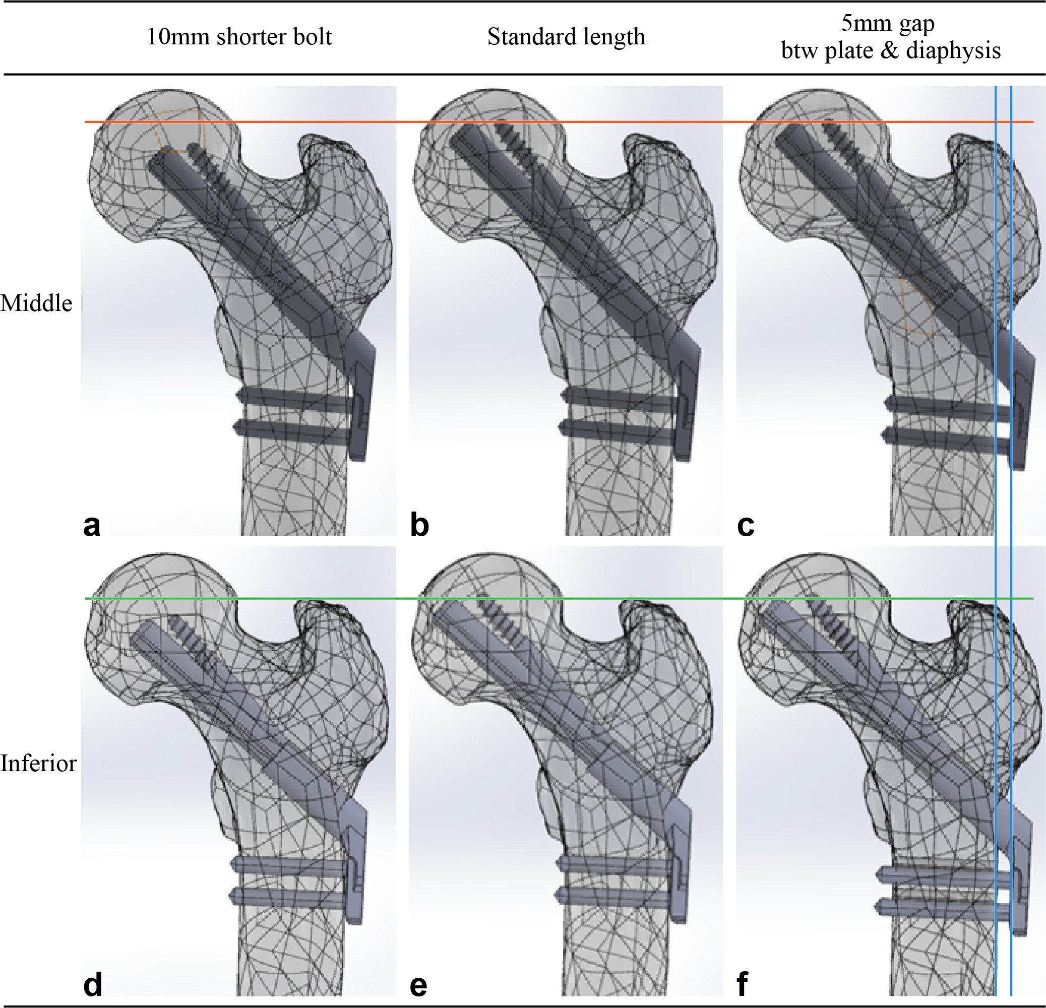
Fig. 1
Femur models with Pauwels III femur neck fracture were virtually fixed with the Femoral Neck System and were established with different combinations of surgical variations. a) to c) The bolt was placed in the central trajectory with respect to the neck cortical corridor in three models in the upper row, while d) to f) the bolt was placed in the inferior trajectory in three models in the lower row. The bolt measured 100 mm in length in the two models in the central column (b, e), which provides the shortest gap between the subchondral bone and implant tip without violating the articular surface. The length of bolts in the two models in the left column (a, d) was 10 mm shorter than the standard bolt. There was a gap between the plate and diaphysis and a 5 mm longer bolt to restore the position of the bolt tip in the two models in the right column (c, f).
Models in which the trajectory of the bolt touched the endocortical bone of 400 Hounsfield units (HU) were defined as inferiorly positioned models. Three inferiorly positioned models were created in the same manner as the centrally positioned models (Figure 1). We used Boolean subtraction to replicate bone loss caused by the drilling and reaming procedure used for FNS insertion.14
Solver
ANSYS 2019 R3 mechanical software (Ansys, USA) was used for the finite element analysis. The mesh of the models was generated using ten-node tetrahedral elements. The mean number of nodes and elements of six finite element models were 6,177,864 (6,172,059 to 6,186,454) and 4,487,265 (4,483,402 to 4,492,613), respectively (Figure 2a, Table I). Elements were generated such that they measured less than 1 mm. Based on the convergence study, the solution was executed without any special error.
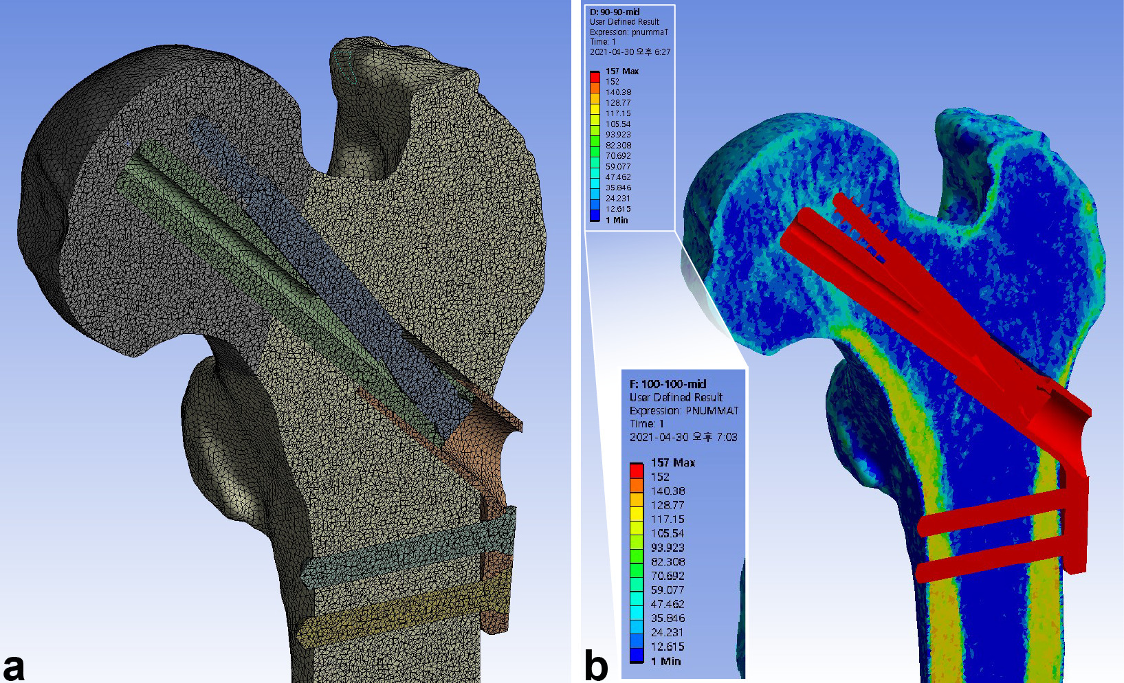
Fig. 2
Meshing of the elements and mapping of the material properties were performed after assembling the femur and implant models. a) The models were meshed into tetrahedral elements with a maximum size of 1 mm, achieving a mean of 6,177,864 nodes (6,172,059 to 6,186,454) and 4,487,265 elements (4,483,402 to 4,492,613). b) The material properties of bone were assigned to the elements using the mapping procedure based on the grey values of the CT scan.
Table I.
Element information consisting of finite elements models.
| Finite elements model | 90-Middle | 100-Middle | 105-Middle | 90-Inferior | 100-Inferior | 105-Inferior |
|---|---|---|---|---|---|---|
| Number of nodes | 6,173,263 | 6,177,003 | 6,186,454 | 6,172,059 | 6,173,326 | 6,185,080 |
| Number of elements | 4,485,557 | 4,486,451 | 4,492,613 | 4,484,310 | 4,483,402 | 4,491,254 |
| Size of element, mm | ||||||
| Mean | 8.56 × 10⁻¹ | 8.56 × 10⁻¹ | 8.56 × 10⁻¹ | 8.56 × 10⁻¹ | 8.56 × 10⁻¹ | 8.56 × 10⁻¹ |
| SD | 9.02 × 10⁻² | 9.04 × 10⁻² | 9.05 × 10⁻² | 9.03 × 10⁻² | 9.02 × 10⁻² | 9.04 × 10⁻² |
| Maximum | 1 | 1 | 1 | 1 | 1 | 1 |
| Minimum | 4.28 × 10⁻² | 4.26 × 10⁻² | 2.84 × 10⁻² | 4.28 × 10⁻² | 4.26 × 10⁻² | 2.84 × 10⁻² |
-
SD, standard deviation.
Boundary conditions
The interface between the locking screws and plate, and the interface between the locking screws and femoral diaphysis, were assumed to be bonded contacts. All the other interfaces between the implant and the two fracture fragments were assumed to be frictional contacts. The friction coefficient for bone-bone interactions, bone-implant interactions, and implant-implant interactions was 0.46, 0.42, and 0.20, respectively.20 The distal condylar articular face was assumed to have a fixed support in the global coordinate system.
Material properties
Material properties were assigned to the bone elements using the mapping methods proposed by Morgan et al21 and the proposed relations between the CT HU, ash density, apparent density, and Young’s modulus.22 This procedure entailed the generation of a map from the CT HU to ash density, and from ash density to apparent density. The mixed relationship reported by Morgan et al21 was used to generate the maps between apparent bone density and Young’s modulus. Bone material properties were classified into 150 groups.23
The Poisson’s ratio of the bone elements was assumed to be 0.3 (Figure 2b).22 The FNS was assumed to be composed of titanium alloy (Ti-6Al-7Nb), whose elastic modulus and Poisson’s ratio were 105 GPa and 0.34, respectively.24 The bone and implant were regarded to be isotropic and linear elastic materials (Table II).
Table II.
Material properties of Titanium – 6% Aluminium – 7% Niobium (Ti-6Al-7Nb).
| Parameters | values |
|---|---|
| Density, gram/cc | 4.52 |
| Young’s modulus, GPa | 105 |
| Yielding strength, MPa | 800 |
| Tensile strength, MPa | 900 |
| Poisson’s ratio | 0.34 |
Loading condition
The femoral head was subjected to load in the single-leg stance in normal gait, according to Bergmann et al’s19 method.25 A resultant vector of 1,752.1 N corresponded to 300% of the body weight.19,20 Simultaneous abductor force was assigned to the greater trochanter.20 We assumed that the load of weight was transferred to the hemisphere of the femoral head, which was abducted by 45° and retroverted by 25° in consideration of the abduction of the acetabulum, and the combined anteversion of the acetabulum and femoral neck (Figure 3). We performed a convergence test for the total strain energy to determine the accuracy of the current finite element models.
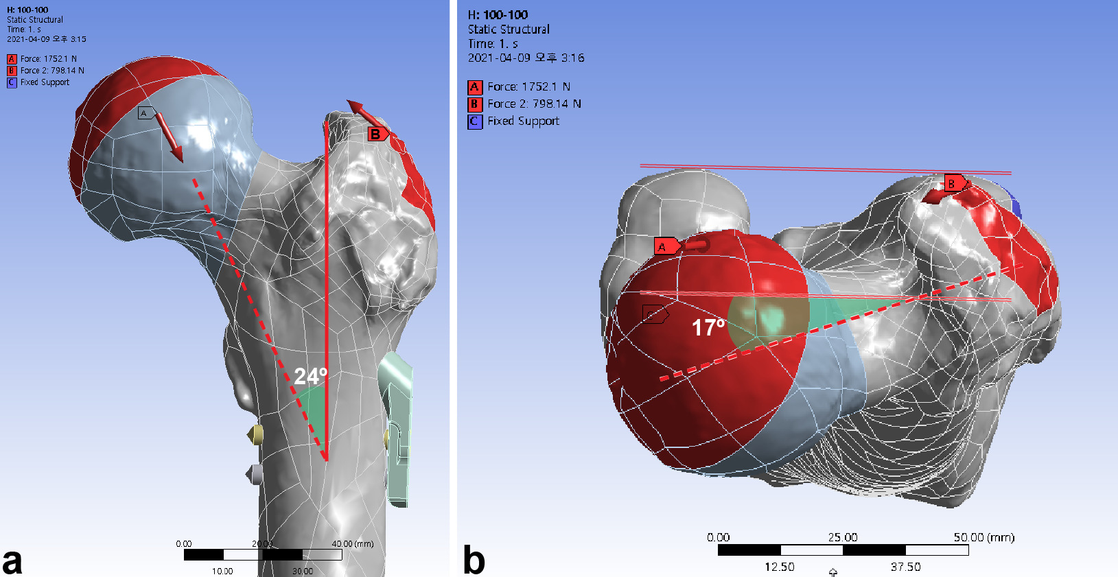
Fig. 3
The femur was loaded in the single-leg stance in each finite element model. a) A load vector of 1,752.2 N corresponds to 300% for a body weight of 59.6 kg. Abductor force was applied to the greater trochanter. b) The load vector (red dashed arrow) had an angle of 24° in the frontal plane and 17° in the axial plane. Weight load (green solid line) was transferred to the surface of hemisphere at an incline of 45° and retroversion of 25°.
Comparative parameters
The mechanical stability of the fracture surface was assessed with interfragmentary gap and sliding. As the loading condition of this study assumed the one-leg stance during normal gait, the results would be interpreted as the amplitude of motion made by cyclic load of normal gait. The total gap and sliding distance were compared, and the resultant compressive and shear stress were assessed.
Statistical analysis
Microsoft Excel (Microsoft, USA) was used for the statistical analysis. Descriptive statistics were used. Less than 5% differences were considered as similar.
Results
With the single-leg stance, the maximum interfragmentary distance of the standard model was 0.070 mm. The use of 10 mm shorter bolts led to a 6.2% to 7.4% increase of the maximum interfragmentary distance. In contrast, a 5 mm gap between the diaphysis and plate decreased the maximum interfragmentary distance by 6.7% to 6.9%. The inferior positioning of FNS had a similar interfragmentary distance with a decrease of 1.2% to 2.5% (Figure 4, Table III).
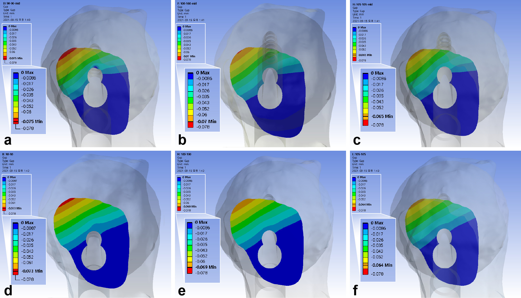
Fig. 4
Band graphs depicting the interfragmentary gap. The results were arranged in the same configuration rule as in Figure 1.
Table III.
The interfragmentary motion and stress on the fracture surface with surgical variation in the Femoral Neck System.
| Variable | Trajectory of bolt | Length of bolt and antirotation screw | ||
|---|---|---|---|---|
| 10 mm shorter bolt | Standard length | 5 mm gap between plate and diaphysis | ||
| Maximum interfragmentary gap (amount of change (reference)) | Centre | 0.075 mm ( + 7.4% (R = 0.070)) | 0.070 mm | 0.065 mm (-6.9% (R = 0.070)) |
| Inferior | 0.073 mm ( + 6.2% (R = 0.069), -2.5% (R = 0.075)) |
0.069 mm (-1.5% (R = 0.070)) | 0.064 mm (-6.7% (R = 0.069), -1.2% (R = 0.065)) |
|
| Maximum interfragmentary sliding distance (amount of change (reference)) | Centre | 0.180 mm ( + 1.0% (R = 0.178)) | 0.178 mm | 0.165 mm (-7.4% (R = 0.178)) |
| Inferior | 0.191 mm ( + 1.3% (R = 0.189), + 6.1% (R = 0.180)) |
0.189 mm ( + 5.8% (R = 0.178)) | 0.175 mm (-7.0% (R = 0.189), + 6.3% (R = 0.165)) |
|
| Maximum interfragmentary compressive stress (amount of change (reference)) | Centre | 11.29 MPa ( + 3.1% (R = 10.96)) | 10.96 MPa | 10.83 MPa (-1.1% (R = 10.96)) |
| Inferior | 15.34 MPa ( + 3.6% (R = 14.81), + 35.9% (R = 11.29)) |
14.81 MPa ( + 35.2% (R = 10.96)) | 14.19 MPa (-4.2% (R = 14.81), + 31.0% (R = 10.83)) |
|
| Maximum interfragmentary shear stress (amount of change (reference)) | Centre | 5.19 MPa ( + 3.0% (R = 5.04)) | 5.04 MPa | 4.98 MPa (-1.2% (R = 5.04)) |
| Inferior | 7.06 MPa ( + 1.9% (R = 6.93), + 36.0% (R = 6.93)) |
6.93 MPa ( + 37.5% (R = 5.04)) | 6.53 MPa (-5.8% (R = 6.93), + 31.1% (R = 4.98)) |
|
-
R, reference.
The maximum interfragmentary sliding distance of the standard model was 0.18 mm. The 5 mm gap between the diaphysis and plate decreased the sliding distance by 7% to 7.4%. The inferior positioning of FNS decreased the distance by 5.7% to 6.2%. The use of 10 mm shorter bolts revealed similar interfragmentary sliding distance with an increase of 1% to 1.3% (Figure 5, Table III).
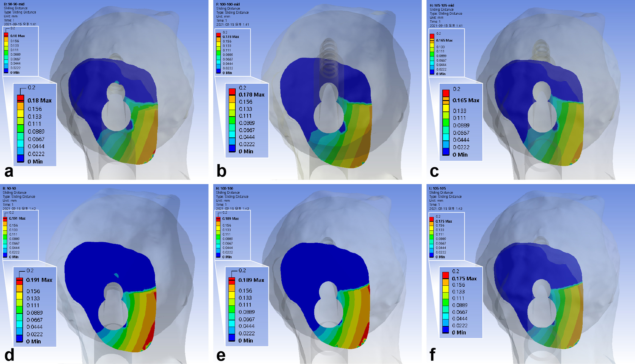
Fig. 5
Band graphs depicting the interfragmentary sliding distance. The results were arranged with the same configuration rule as in Figure 1.
The maximum interfragmentary compressive stress was 10.96 MPa. The inferior positioning of FNS increased interfragmentary compressive stress by 31.0% to 35.9%. The use of 10 mm shorter bolts increased the compressive stress by 3.1% to 3.6%, while a 5 mm gap between the diaphysis and plate decreased it by 1.1% to 4.2%. (Figure 6, Table III)
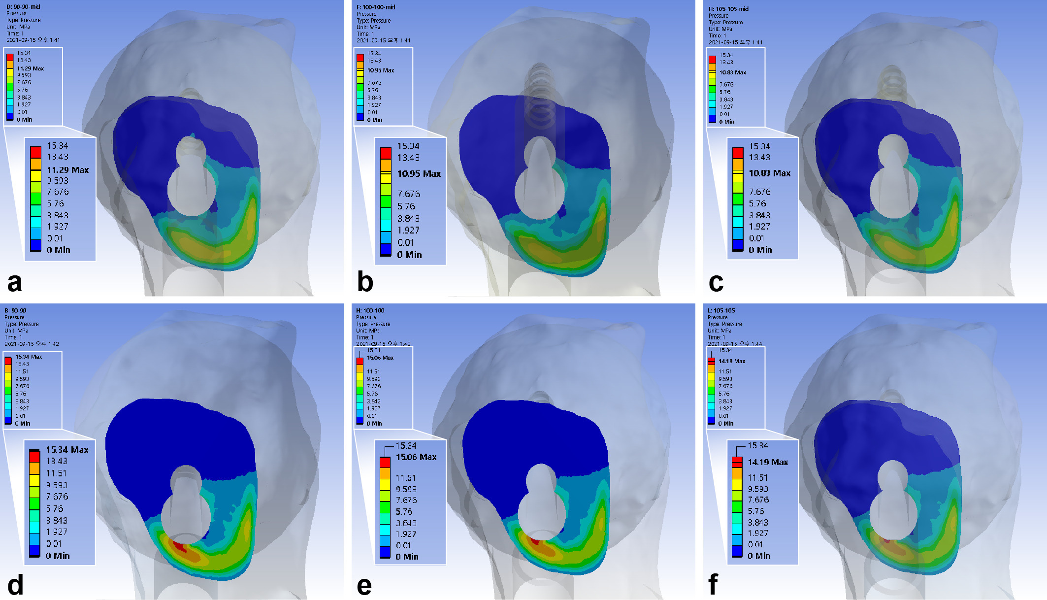
Fig. 6
Band graphs depicting the interfragmentary compression. The results were arranged with the same configuration rule as in Figure 1.
The maximum interfragmentary shear stress was 5.04 MPa. The inferior positioning of FNS increased the shear stresses by 31.0% to 36.0%, 10 mm shorter bolts increased it by 1.9% to 3.0%, while a 5 mm gap between diaphysis and plate decreased it by 1.2% to 5.8% (Figure 7, Table III).
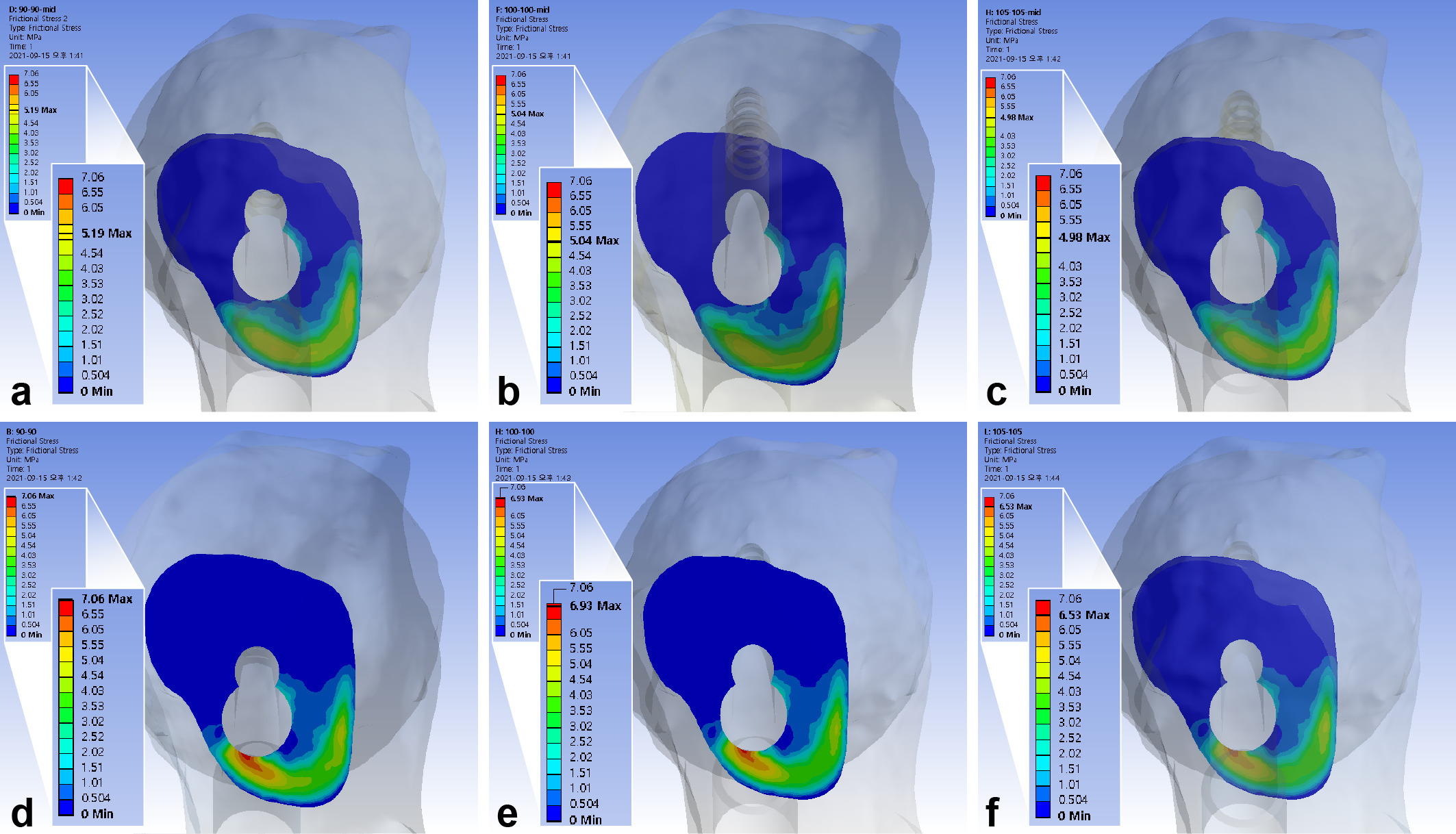
Fig. 7
Band graphs depicting the interfragmentary shear stress. The results were arranged with the same configuration rule as in Figure 1.
Discussion
The standard procedure for FNS guides the surgeon to place the bolt in the central trajectory without a gap between the lateral cortex and plate. The present finite element analysis found that inferior positioning of bolt increased the interfragmentary transverse movement, and usage of short bolt increased the interfragmentary gap, while a single stance load was applied on the femoral head. Placing the gap between the lateral cortex of the FNS for Pauwels type III femur neck fracture provides comparable stability to the standard method, suggesting that fine control of bolt depth could be achieved by placing a gap between the diaphysis and plate without mechanical disadvantage.
Mechanobiological theory regarding fracture-healing assumes that the mechanical environment around a fracture affects the healing process.26 The influence on bone-healing can be varied with direction, amount, rate, and control of motion.26 Previous experiments have indicated that asymmetric axial or transverse motion have negative effects, while a certain amount of cyclic axial motion has a positive effect on fracture-healing. According to previous combined experimental observations with finite element analysis, asymmetric axial or transverse motion tend to decrease the volume of a callus.27 An in vivo experiment to assess the effect of interfragmentary motion concluded that transverse motion, relative to axial motion, delayed bone healing.28
Most mechanobiological experiments were performed with a diaphyseal fracture model, with mechanical and biological environment different from that of femoral neck fracture. The femur neck with inherently bent morphology is designed to bear the eccentric load, and the intracapsular location provides a different biological environment. With a paucity of research regarding mechanical effect on bone-healing in femoral neck fracture, insights from these experiments were applied to interpret results of the present study.
Inferior placement of the FNS constricts the area below the implant’s penetration of fracture surface to a narrower space. A previous finite element analysis, which compared the effect of the trajectory of the cephalic screw on the trochanteric fracture surface, reported that implants with a lower caput–collum–diaphysis angle penetrated the superior fracture surface, and had a favourable mechanical environment for fracture-healing if the tip of the screw was positioned in the same location.29 A wider area below the screw may be dispersed if subjected to the load of single-leg stance.29 Adding to the increase of compressive stress, interfragmentary shear stress also increased by 31% to 36% compared to central positioning of bolt.
The gap between the implant tip and subchondral bone is important for stable fixation during femoral neck fracture surgery using MCS.30,31 According to Rau et al,32 the insertion of the DHS into the subchondral bone of the femoral head gave satisfactory clinical results. The tip-apex distance, determined by the length of the DHS during intertrochanteric fracture surgery, was also reported to be an important factor associated with fixation failure.15 The present study also advocates the approximation of the bolt closer to the subchondral bone for better stability.
Previous studies reported that the use of a locking compression plate (LCP) for fracture fixation can obtain more rigid fixation compared to the conventional screw; however, the rigidity of the fixation may decrease and lead to structural failure, if the gap between plate and the bone increases.33 Ahmad et al34 conducted a mechanical stability analysis of the LCP and reported that a gap of 5 mm between the bone and LCP increases plastic deformation of the LCP. Thus, they insisted that the distance between the bone and LCP should be less than 2 mm. Although the FNS plate also has a locking mechanism, our study found that a 5 mm gap between the plate and diaphysis preserved the interfragmentary stability. This is probably because the FNS plate has barrels to support the assembly of the bolt and antirotation screw. The gap between the plate and diaphysis provides the longer corridor of bone and metal barrel which support the bolt.
With the 3.5 mm length of pitch, the lag screw of DHS provides a 1.75 mm minimum unit of depth adjustment, which is comparable to the advance made by a half-turn of the screw. In contrast, the depth of bolt in FNS is difficult to finely control because the instrument provides the length in 5 mm units (75 mm, 80 mm, 85 mm, etc.).35 Although the method of fine control has been introduced before, placing a gap between the plate and diaphysis can be another way to control the depth of bolt without violation of subchondral bone and great loss of mechanical stability.35
There are several limitations to our study. There is skepticism as to whether our findings will correspond to actual clinical results, because finite element analysis uses various assumptions for simplification (e.g. ‘the bone and implant were regarded to be isotropic and linear elastic materials’). Although the finite element model of the femur was modelled from CT images of an elderly patient who suffered from Pauwels type II femoral neck fracture, we assumed that the femur was composed of an isotropic and elastic material. Mapping of material properties based on the grey values of the CT scan may help bridge the gap between simulation and the real-world setting. Moreover, our results were not validated with experiments in this study. Instead, the validity of the finite element model was considered to be acceptable based on the convergence study.
The relatively small amount of difference in absolute values might add skepticism. The outcome of fracture treatment was known to be affected by various patient-, surgeon-, and fracture-related factors.36 Since the influence of these factors (except for target position of implant) was not within the scope of our analysis, we assumed that all surgical targets were achieved, especially complete reduction of fracture. Moreover, the study focused on the comparison of target position of implant. We believe that insights drawn from this study will add to existing knowledge on various determinants contributing significant differences in fracture treatment.
In conclusion, compared to the standard centrally positioned model, shortening the insertion of the bolt of FNS by 10 mm and positioning it in the inferior femoral neck cortical corridor rendered more interfragmentary motion in the finite element models of Pauwels III femur neck fracture. The bolt in the inferior trajectory rendered concentration of interfragmentary compressive and shear stress. Placing a gap between FNS plate and diaphysis has comparable stability to the standard models. Thus, we believe that the central position of the bolt in the neck cortical corridor, and fine control of the bolt tip close to subchondral bone of femoral head, is an important surgical target in the fixation of Pauwels III femur neck fracture. The placing of a gap between femoral diaphysis and plate can be a good option to control the length of the bolt.
References
1. Ly TV , Swiontkowski MF . Treatment of femoral neck fractures in young adults . J Bone Joint Surg Am . 2008 ; 90-A ( 10 ): 2254 – 2266 . PubMed Google Scholar
2. Nowotarski PJ , Ervin B , Weatherby B , Pettit J , Goulet R , Norris B . Biomechanical analysis of a novel femoral neck locking plate for treatment of vertical shear Pauwel’s type C femoral neck fractures . Injury . 2012 ; 43 ( 6 ): 802 – 806 . Google Scholar
3. Shen M , Wang C , Chen H , Rui YF , Zhao S . An update on the Pauwels classification . J Orthop Surg Res . 2016 ; 11 ( 1 ): 161 . Crossref PubMed Google Scholar
4. Cha Y-H , Yoo J-I , Hwang S-Y , et al. Biomechanical evaluation of internal fixation of Pauwels Type III femoral neck fractures: a systematic review of various fixation methods . Clin Orthop Surg . 2019 ; 11 ( 1 ): 1 – 14 . Crossref PubMed Google Scholar
5. Kang JS , Moon KH , Shin JS , Shin EH , Ahn CH , Choi GH . Clinical results of internal fixation of subcapital femoral neck fractures . Clin Orthop Surg . 2016 ; 8 ( 2 ): 146 – 152 . Crossref PubMed Google Scholar
6. Knobe M , Altgassen S , Maier K-J , et al. Screw-blade fixation systems in Pauwels three femoral neck fractures: a biomechanical evaluation . Int Orthop . 2018 ; 42 ( 2 ): 409 – 418 . Crossref PubMed Google Scholar
7. Kain MS , Marcantonio AJ , Iorio R . Revision surgery occurs frequently after percutaneous fixation of stable femoral neck fractures in elderly patients . Clin Orthop Relat Res . 2014 ; 472 ( 12 ): 4010 – 4014 . Crossref PubMed Google Scholar
8. Keating JF , Grant A , Masson M , Scott NW , Forbes JF . Randomized comparison of reduction and fixation, bipolar hemiarthroplasty, and total hip arthroplasty. Treatment of displaced intracapsular hip fractures in healthy older patients . J Bone Joint Surg Am . 2006 ; 88-A ( 2 ): 249 – 260 . Crossref PubMed Google Scholar
9. Sheikh HQ , Hossain FS , Aqil A , Akinbamijo B , Mushtaq V , Kapoor H . A comprehensive analysis of the causes and predictors of 30-day mortality following hip fracture surgery . Clin Orthop Surg . 2017 ; 9 ( 1 ): 10 – 18 . Crossref PubMed Google Scholar
10. Bliven E , Sandriesser S , Augat P , von Rüden C , Hackl S . Biomechanical evaluation of locked plating fixation for unstable femoral neck fractures . Bone Joint Res . 2020 ; 9 ( 6 ): 314 – 321 . Crossref PubMed Google Scholar
11. Stoffel K , Zderic I , Gras F , et al. Biomechanical evaluation of the femoral neck system in unstable Pauwels III femoral neck fractures: a comparison with the dynamic hip screw and cannulated screws . J Orthop Trauma . 2017 ; 31 ( 3 ): 131 – 137 . Crossref PubMed Google Scholar
12. Johnson JP , Borenstein TR , Waryasz GR , et al. Vertically oriented femoral neck fractures: a biomechanical comparison of 3 fixation constructs . J Orthop Trauma . 2017 ; 31 ( 7 ): 363 – 368 . Crossref PubMed Google Scholar
13. Samsami S , Saberi S , Sadighi S , Rouhi G . Comparison of three fixation methods for femoral neck fracture in young adults: experimental and numerical investigations . J Med Biol Eng . 2015 ; 35 ( 5 ): 566 – 579 . Crossref PubMed Google Scholar
14. No authors listed . Surgical Technique of FNS System . DePuy Synthes Companies . 2021 . https://www.jnjmedicaldevices.com/en-US/product/femoral-neck-system-fns ( date last accessed 15 September 2021 ). Google Scholar
15. Baumgaertner MR , Curtin SL , Lindskog DM , Keggi JM . The value of the tip-apex distance in predicting failure of fixation of peritrochanteric fractures of the hip . J Bone Joint Surg Am . 1995 ; 77-A ( 7 ): 1058 – 1064 . PubMed Google Scholar
16. Cha Y , Song JU , Yoo JI , et al. Improved control over implant anchorage under the use of the femoral neck system for fixation of femoral neck fractures: a technical note . BMC Musculoskelet Disord . 2021 ; 22 ( 1 ): 621 . Crossref PubMed Google Scholar
17. Cho HJ , Kwak DS , Kim IB . Morphometric Evaluation of Korean Femurs by Geometric Computation: Comparisons of the Sex and the Population . Biomed Res Int . 2015 ; 2015 : 730538 . Crossref PubMed Google Scholar
18. Parker MJ , Dynan Y . Is Pauwels classification still valid? Injury . 1998 ; 29 ( 7 ): 521 – 523 . Crossref PubMed Google Scholar
19. Bergmann G , Graichen F , Rohlmann A . Hip joint loading during walking and running, measured in two patients . J Biomech . 1993 ; 26 ( 8 ): 969 – 990 . Crossref PubMed Google Scholar
20. Lee P-Y , Lin K-J , Wei H-W , et al. Biomechanical effect of different femoral neck blade position on the fixation of intertrochanteric fracture: a finite element analysis . Biomed Tech (Berl) . 2016 ; 61 ( 3 ): 331 – 336 . Crossref PubMed Google Scholar
21. Morgan EF , Bayraktar HH , Keaveny TM . Trabecular bone modulus-density relationships depend on anatomic site . J Biomech . 2003 ; 36 ( 7 ): 897 – 904 . Crossref PubMed Google Scholar
22. Taddei F , Schileo E , Helgason B , Cristofolini L , Viceconti M . The material mapping strategy influences the accuracy of CT-based finite element models of bones: an evaluation against experimental measurements . Med Eng Phys . 2007 ; 29 ( 9 ): 973 – 979 . Crossref PubMed Google Scholar
23. Nolte D , Bull AMJ . Femur finite element model instantiation from partial anatomies using statistical shape and appearance models . Med Eng Phys . 2019 ; 67 : 55 – 65 . Crossref PubMed Google Scholar
24. No authors listed . ASTM F1295-16: Standard Specification for Wrought Titanium-6Aluminum-7Niobium Alloy for Surgical Implant Applications (UNS R56700) . ASTM International , 2016 . https://www.astm.org/f1295-16.html ( date last accessed 15 January 2021 ). Google Scholar
25. Morlock M , Schneider E , Bluhm A , et al. Duration and frequency of every day activities in total hip patients . J Biomech . 2001 ; 34 ( 7 ): 873 – 881 . Crossref PubMed Google Scholar
26. Epari DR , Duda GN , Thompson MS . Mechanobiology of bone healing and regeneration: in vivo models . Proc Inst Mech Eng H . 2010 ; 224 ( 12 ): 1543 – 1553 . Crossref PubMed Google Scholar
27. Elkins J , Marsh JL , Lujan T , et al. Motion predicts clinical callus formation: construct-specific finite element analysis of supracondylar femoral fractures . J Bone Joint Surg Am . 2016 ; 98-A ( 4 ): 276 – 284 . Crossref PubMed Google Scholar
28. Augat P , Burger J , Schorlemmer S , Henke T , Peraus M , Claes L . Shear movement at the fracture site delays healing in a diaphyseal fracture model . J Orthop Res . 2003 ; 21 ( 6 ): 1011 – 1017 . Crossref PubMed Google Scholar
29. Kim J-T , Jung C-H , Shen QH , et al. Mechanical effect of different implant caput-collum-diaphyseal angles on the fracture surface after fixation of an unstable intertrochanteric fracture: a finite element analysis . Asian J Surg . 2019 ; 42 ( 11 ): 947 – 956 . Crossref PubMed Google Scholar
30. Ehlinger M , Favreau H , Eichler D , Adam P , Bonnomet F . Early mechanical complications following fixation of proximal femur fractures: from prevention to treatment . Orthop Traumatol Surg Res . 2020 ; 106 ( 1S ): S79 – S87 . Crossref PubMed Google Scholar
31. Lindequist S . Cortical screw support in femoral neck fractures. A radiographic analysis of 87 fractures with a new mensuration technique . Acta Orthop Scand . 1993 ; 64 ( 3 ): 289 – 293 . Crossref PubMed Google Scholar
32. Rau FD , Manoli A , Morawa LG . Treatment of femoral neck fractures with the sliding compression screw . Clin Orthop Relat Res . 1982 ; 163 : 137 – 140 . PubMed Google Scholar
33. Feng YJ , Lin KP , Tsai CL , Wei HW . Influence of gap distance between bone and plate on structural stiffness and parallel interfragmental movement in far-cortical locking technique - a biomechanical study . Comput Methods Biomech Biomed Engin . 2021 ; 24 ( 11 ): 1206 – 1211 . Crossref PubMed Google Scholar
34. Ahmad M , Nanda R , Bajwa AS , Candal-Couto J , Green S , Hui AC . Biomechanical testing of the locking compression plate: when does the distance between bone and implant significantly reduce construct stability? Injury . 2007 ; 38 ( 3 ): 358 – 364 . Crossref PubMed Google Scholar
35. Cha Y , Song J-U , Yoo J-I , et al. Improved control over implant anchorage under the use of the femoral neck system for fixation of femoral neck fractures: a technical note . BMC Musculoskelet Disord . 2021 ; 22 ( 1 ): 621 . Crossref PubMed Google Scholar
36. Bojan AJ , Beimel C , Taglang G , Collin D , Ekholm C , Jönsson A . Critical factors in cut-out complication after Gamma Nail treatment of proximal femoral fractures . BMC Musculoskelet Disord . 2013 ; 14 : 1 . Crossref PubMed Google Scholar
Author contributions
C-H. Jung: Data curation, Formal analysis, Investigation, Methodology, Software, Visualization.
Y. Cha: Supervision, Writing – original draft.
H. S. Yoon: Writing – review & editing.
C. H. Park: Conceptualization, Writing – original draft.
J-I. Yoo: Supervision, Writing – review & editing.
J-T. Kim: Conceptualization, Project administration, Supervision.
Y. Jeon: Investigation, Methodology, Software.
Funding statement
The authors received no financial or material support for the research, authorship, and/or publication of this article.
Acknowledgements
We wish to thank Dentium (Seoul, Korea) for assistance with the reconstruction of the finite element models and virtual surgery with 3D models using MIMICS Research 22.0, 3-matic 14, NRecon, and Solidworks 2019. This research received no specific grant from any funding agency in the public, commercial or not-for-profit sectors.
Ethical review statement
This study complies with the Declaration of Helsinki. The requirement for informed consent was waived, and the study protocol was approved by the institutional review board (IRB) of our hospital, as the acquisition of CT scans was part of routine care and the use of the data posed minimal risk of harm to the patient (IRB number: AJIRB-MED-MDB-21-026).
Open access funding
The authors confirm that the open access fee for this study was self-funded.
© 2022 Author(s) et al. This is an open-access article distributed under the terms of the Creative Commons Attribution Non-Commercial No Derivatives (CC BY-NC-ND 4.0) licence, which permits the copying and redistribution of the work only, and provided the original author and source are credited. See https://creativecommons.org/licenses/by-nc-nd/4.0/.
